Analog inputs can be mV, Volts, mili-Amps, Amps, AC, DC, or complex wave forms. Typical process controls applications take these measurements from sensors and transducers and convert them to 4 - 20 mA signal. There is still a huge infrastructure in most industries that support this. The 4 mA level represents a 0% measurement value, the 20 mA level represents the 100% measurement value. This provides an opportunity to signal a fault condition either intentionally by the transmitter or a unintentionally by a cut cable for example.
This design is based on the MCP3208 8 channel 12 Bit Analog to Digital converter form Microchip.
PCB Assembly complete with PIC Processor Module:

Schematic:
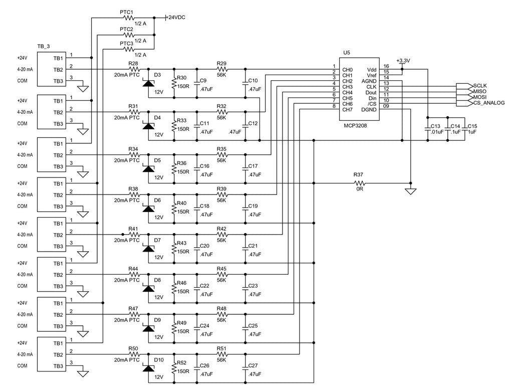
Each analog input 0 to 20 mA signal is convert to a voltage across the 150 Ohm Load Resistor giving a 0 to 3.0 V input to the MCP3208.
PCB Assembly with PIC Processor PCB detached:

Some of the design criteria was to have the module be compatible with the Raspberry Pi, have RS485 I/O, have MODBUS RTU communication and have protection for the input circuits.
Here is the full specification:
Specifications:
- Power: 24 VDC
- RS485 Jumper Selectable 9600 or 19.2K Baud, N81
- Modbus RTU Protocol
- Modbus ID: Dipswitch Selectable
- Analog Inputs: 4-20 mA into 150 Ohm load, PTC Fuse Protection
- Resolution: 12 Bit ADC
- Calibration: Simple calibration via jumpers
Processor:
- PIC18F45K20, c/w ICSP Port
Indicators:
- Power On: BLUE LED
- Analog Input: 1 thru 8: GREEN LED ON when input above 2mA
- Heart Beat: AMBER LED (Flashes to indicate proper operation)
- RS485: GREEN LED Rx, RED LED Tx.
Options:
- DIN Rail Enclosure Bud Industries Model: DMB-4774
Schematic Page 2:
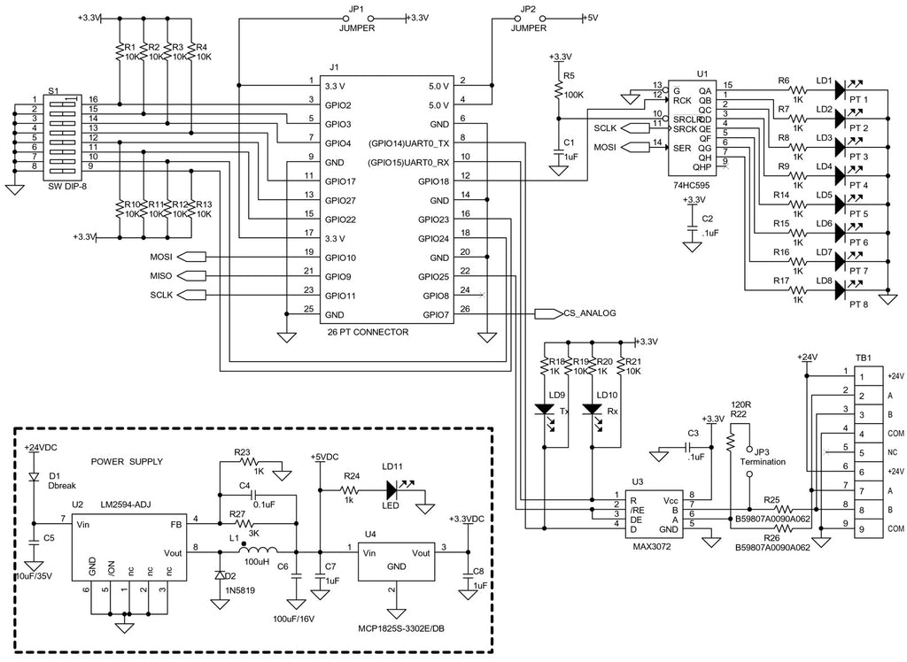
By removing the PIC PCB, the device now becomes Raspberry Pi Compatible:

For information regarding the PIC module, please see the post for the VP-EC-8KO.
Sample Source Code
This sample code uses the wiringPi library and the Geany C compiler. The code has been tested for:
- Reading the Dipswitch
- Reading the 8 channels of AD Counts from the MCP3208 AD Converter
- 20 mA into a 150 Ohm load resistor = 3.0 VDC
- MCP3208 uses the 3.3 VDC as a reference, therefore 20 mA = 3/3.3 * 4096 = 3723 AD Counts
- A1 thru A8 LED driver using the 74HC595 Serial Shift Register
/*
* main.c
*
* Copyright 2016 <pi@raspberrypi>
*
* This program is free software; you can redistribute it and/or modify
* it under the terms of the GNU General Public License as published by
* the Free Software Foundation; either version 2 of the License, or
* (at your option) any later version.
*
* This program is distributed in the hope that it will be useful,
* but WITHOUT ANY WARRANTY; without even the implied warranty of
* MERCHANTABILITY or FITNESS FOR A PARTICULAR PURPOSE. See the
* GNU General Public License for more details.
*
* You should have received a copy of the GNU General Public License
* along with this program; if not, write to the Free Software
* Foundation, Inc., 51 Franklin Street, Fifth Floor, Boston,
* MA 02110-1301, USA.
*
*
*/
#include <stdio.h>
#include <string.h>
#include <errno.h>
#include <stdlib.h>
#include <wiringPi.h>
#include <wiringPiSPI.h>
// Define Pins RPi V2 Series B
#define PIN_SW1 2
#define PIN_SW2 3
#define PIN_SW3 4
#define PIN_SW4 17
#define PIN_SW5 27
#define PIN_SW6 22
#define PIN_SW7 24
#define PIN_SW8 23
#define PIN_08 14 // Used for testing UART Leds Tx and Rx
#define PIN_10 15
#define PIN_EN_LED 18 // CS for LEDS (74HC595)
#define PIN_EN_AD 7 // CS for Analog Inputs MCP3208
#define mA_20 3723 // 20 mA * 150Ohms = 3 Vdc/3.3 Vdc full scale * 4096 Counts
#define mA_Fault 372 // 2 mA Fault level in AD Counts
// Function Prototypes
void Initialize_Pi_Hardware(void);
int Read_Switch(void);
void Update_Leds(void);
unsigned int Update_Analog(unsigned char channel);
// Variables
unsigned int AN_AD[8];
int Switch;
int main(void) {
int i;
wiringPiSetupGpio(); // Initialize the wiringPi GPIO
Initialize_Pi_Hardware(); // Set the GPIO Bit directions
digitalWrite(PIN_EN_LED, HIGH); // Set the EN LED CS HIGH
digitalWrite(PIN_EN_AD, HIGH); // Set the EN AD CS HIGH
while(1)
{
Switch = Read_Switch(); // Read the 8 Point Dip Switch
AN_AD[0] = Update_Analog(0); // Read Channel A0 AD Counts from MCP3208
AN_AD[1] = Update_Analog(1); // Read Channel A1 AD Counts
AN_AD[2] = Update_Analog(2); // Read Channel A2 AD Counts
AN_AD[3] = Update_Analog(3); // Read Channel A3 AD Counts
AN_AD[4] = Update_Analog(4); // Read Channel A4 AD Counts
AN_AD[5] = Update_Analog(5); // Read Channel A5 AD Counts
AN_AD[6] = Update_Analog(6); // Read Channel A6 AD Counts
AN_AD[7] = Update_Analog(7); // Read Channel A7 AD Counts
printf("ID = %d \n", Switch); // Print the Data
for(i = 0; i < 8; i++) {
printf("Channel AN%d = %d ADC, %0.2f mA \n", (i+1), AN_AD[i], (float)AN_AD[i] * 20 / mA_20);
}
printf("\n");
Update_Leds(); // Update AN1 thru A8 LEDs using the 74HC595
delay(1000); // Delay 1 Second loop
}
return 0;
}
// Update Analog Inputs using the MCP3208
unsigned int Update_Analog(unsigned char channel) {
unsigned int adc, input;
unsigned char buf[3];
wiringPiSPISetup(1, 100000);
input = 0x0600 | (channel << 6);
buf[0] = (input >> 8) & 0xff;
buf[1] = input & 0xff;
buf[2] = 0;
digitalWrite(PIN_EN_AD, LOW);
wiringPiSPIDataRW(1,buf,3);
adc = ((buf[1] & 0x0f ) << 8) | buf[2];
digitalWrite(PIN_EN_AD, HIGH);
return adc;
}
// Update the A1 thru A8 LEDs using the 74HC595
// If the AD Counts are > than the AD Fault Counts, the respective Ax LED turns on
void Update_Leds(void) {
unsigned char buf[2];
unsigned char value;
value = 0;
if(AN_AD[0] > mA_Fault) {
value |= 0x01;
}
if(AN_AD[1] > mA_Fault) {
value |= 0x02;
}
if(AN_AD[2] > mA_Fault) {
value |= 0x04;
}
if(AN_AD[3] > mA_Fault) {
value |= 0x08;
}
if(AN_AD[4] > mA_Fault) {
value |= 0x10;
}
if(AN_AD[5] > mA_Fault) {
value |= 0x20;
}
if(AN_AD[6] > mA_Fault) {
value |= 0x40;
}
if(AN_AD[7] > mA_Fault) {
value |= 0x80;
}
buf[0] = value;
wiringPiSPISetup(0, 100000);
wiringPiSPIDataRW(0,buf,1);
digitalWrite(PIN_EN_LED, LOW);
delay(1);
digitalWrite(PIN_EN_LED, HIGH);
}
// Read the Dipswitch as a value from 0 thru 255, to be used as the Modbus ID value
int Read_Switch(void) {
int value;
value = 0;
if(!digitalRead(PIN_SW1)) {
value |= 0x01;
}
if(!digitalRead(PIN_SW2)) {
value |= 0x02;
}
if(!digitalRead(PIN_SW3)) {
value |= 0x04;
}
if(!digitalRead(PIN_SW4)) {
value |= 0x08;
}
if(!digitalRead(PIN_SW5)) {
value |= 0x10;
}
if(!digitalRead(PIN_SW6)) {
value |= 0x20;
}
if(!digitalRead(PIN_SW7)) {
value |= 0x40;
}
if(!digitalRead(PIN_SW8)) {
value |= 0x80;
}
return value;
}
// Initialze the GPIO pin directions
void Initialize_Pi_Hardware(void) {
pinMode(PIN_08, OUTPUT);
pinMode(PIN_10, OUTPUT);
pinMode(PIN_EN_LED, OUTPUT);
pinMode(PIN_EN_AD, OUTPUT);
pinMode(PIN_SW1, INPUT);
pinMode(PIN_SW2, INPUT);
pinMode(PIN_SW3, INPUT);
pinMode(PIN_SW4, INPUT);
pinMode(PIN_SW5, INPUT);
pinMode(PIN_SW6, INPUT);
pinMode(PIN_SW7, INPUT);
pinMode(PIN_SW8, INPUT);
}