SDAFE - Software Defined Analog Input I/O Module
Regular price
$49.00 USD
Each SDAFE™ Analog I/O Module can be programmed thru the application software to be 4-20 mA, 1 to 15 VDC or 0 to 10 VDC input. All modules are factory calibrated with 6 break point calibration per input type.
Typical resolutions are +/- .005 mA for 0 thru 20 mA. +/- .005 VDC for 0 to 5 VDC and 0 to 10 VDC Inputs.
The SDAFE™ communicates via SPI, and is powered from a single +3.3VDC or +5VDC source. The A/D converter is a 15 bit A/D.
Two module types are available:
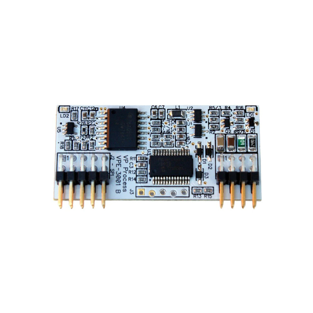
Isolated SDAFE™ Model VPE-3001B

The SDAFE™ is an isolated analog signal conditioner. Inputs can be software selected to be either mA or VDC in various ranges and unit types. Signal and power isolation based on the Analog Devices, Inc., iCoupler® technology,
The Isolator Integrated Circuit carries the following Safety and Regulatory Approvals:
- UL recognition
- 2500 V rms for 1 minute per UL 1577
- CSA Component Acceptance Notice #5A
- VDE certificate of conformity (pending)
- IEC 60747-5-2 (VDE 0884, Part 2)
- VIORM= 560 V peak
Non-Isolated SDAFE™ Model VPE-3051A

This I/O Module is the same as above without the isolation.
Standard Ranges:
- 0 - 20 mA
- 0 - 5 VDC
- 0 - 10 VDC
 The SDAFE™ Manual
The PI-SPI-DIN-SDAFE Expansion I/O Module holds up to 4 SDAFE™ I/O Modules (Sold Separately)

Specifications:
Power:
3.3VDC or 5.0VDC (Raspberry Pi and Arduino Compatible)
SPI:
MISO Data Input, Active High
MOSI Data Output, Active High During Chip Select, Open Collector Output
SCK Clock
/CS Chip Select, Active Low
Speed Up to 100KHz
Input:
Type 1: (Default) 0 - 20 mA 0 - 20000 Units: mA
Type 2: 0 - 20 mA 0 - 10000 %
Type 3: 4 - 20 mA 0 - 10000 %
Type 4: (Default) 0 - 5 VDC 0 - 5000 Units: VDC
Type 5: 0 - 5 VDC 0 - 10000 %
Type 6: 1 - 5 VDC 0 - 10000 %
Type 7: (Default) 0 - 10 VDC 0 - 10000 Units: VDC
Type 8: 0 - 10 VDC 0 - 10000 %
Type 9: 2 - 10 VDC 0 - 10000 %
AD Converter:
Resolution: 15 bits
Conversion:
15 SPS (Samples per Second)
Accuracy:
+/- .005 reading for mA and VDC Types 1, 4 and 7
+/- .01 reading for mA and VDC Types 2, 3, 5, 6, 8 and 9
Over Range:
Inputs have up to 25% Over Range per input type
Error Status:
Status Register: Over Range Detection when input greater than 125%
Reverse Polarity Detection
Indicators:
Blue LED: Power ON
Green LED: ON When Chip Select Active (Low)
Connections:
J2 Non-Isolated Side
Pin 1: +V (+3.3VDC or +5VDC)
Pin 2: 0V (Common)
Pin 3: MOSI
Pin 4: CLK
Pin 5: /SS (Chip Select)
Pin 6: MISO
Pin 7: no connection (Reserved for HART Module)
Pin 8: no connection (Reserved for HART Module)
Pin 9: no connection (Reserved for HART Module)
Pin 10: no connection (Reserved for HART Module)
J1 Isolated Side (Non-Isolated Side for VPE-3051A)
Pin 1: no connection
Pin 2: no connection
Pin 3: Common
Pin 4: Common
Pin 5: Signal Input mA or VDC
Pin 6: Signal Input mA or VDC
Pin 7: Common
Pin 8: Common
Dimensions:
1.95" x 0.95"
Headers on standard 0.1" spacing
