When the design team at Widgetlords Electronics started designing the WL-MIO system, one of the main design criteria was to have the capability of redundant power supplies.
Some industrial automation applications require “High Reliability”, where control modules and power supplies can be “hot swapped” without shutting down the control systems.
By having two or more power supplies installed in the same system or backplane, if a fault condition is detected on a power supply, the faulty power supply can be pulled out of the system’s backplane while the system is still running. The other installed power supply (or supplies) take up the full load, until a replacement power supply can be re-installed. During this “hot swap” process, the main controller ie: the Raspberry Pi 4, must be supplied with a constant 5.1 VDC to prevent a brownout condition or total lack of power.
The RPi 4 (and Rpi 3’s) have a power monitor IC that will trigger an undervoltage alarm if the power voltage drops below 4.63 VDC.
Here is the block diagram of the WL-MIO Power Supply, the VPE-6010

The VPE-6010 Power Supply delivers 5.1A at 4A to the backplane it is plugged into. The output goes through an “Ideal Diode” circuit that monitors the load, and regulates the output. Typically, the voltage drop across the Ideal Diode is about 20 mV DC, whereas in traditional auctioneering diode circuits the voltage drop can be between .2 to .7 VDC, depending on the type of diodes used.
For example, from the above block diagram, the V1 and V2 inputs go through Schottky Diodes. The voltage drop across the diode used is typically about .55 VDC at 5A. In the input circuit, this is acceptable. For a regulated 5 VDC output to power a Raspberry Pi, this would not work.
By using the Ideal Diode configuration, another benefit is load sharing. For example, if the load on the 5.1 VDC supply is 3 A (Raspberry Pi 4 plus other modules in the backplane) and 2 VPE-6010 power supplies are used, the load off each supply would be 1.5 A. If one supply had to be replaced, simply unplugging the the module would transfer the full load to the remaining power supply, which can handle the load on it’s own, and would not cause the Raspberry Pi to go into a fault condition. Once the new power supply is plugged in, the Ideal Diode circuitry kicks back in and allows both supplies to share the load once again.
Here is a picture of the VPE-6010 Power Supply:

A complete description and specification for the VPE-6010 can be found on the wlmio.com website.
Each of the VPE-6010 power supplies used in the WL-MIO system has a complete “health” monitor built in where the user under program control can read:
- V1 Input Voltage
- V2 Input Voltage
- +V Field Voltage available to the backplane
- +V Current being used by the backplane
- +5.1 VDC Output to the backplane
- +5.1 VDC Current being used by the backplane
Sample Python code for the VPE-6010 Power Supply can be found in the WL-MIO-AN-36010 Application Note.
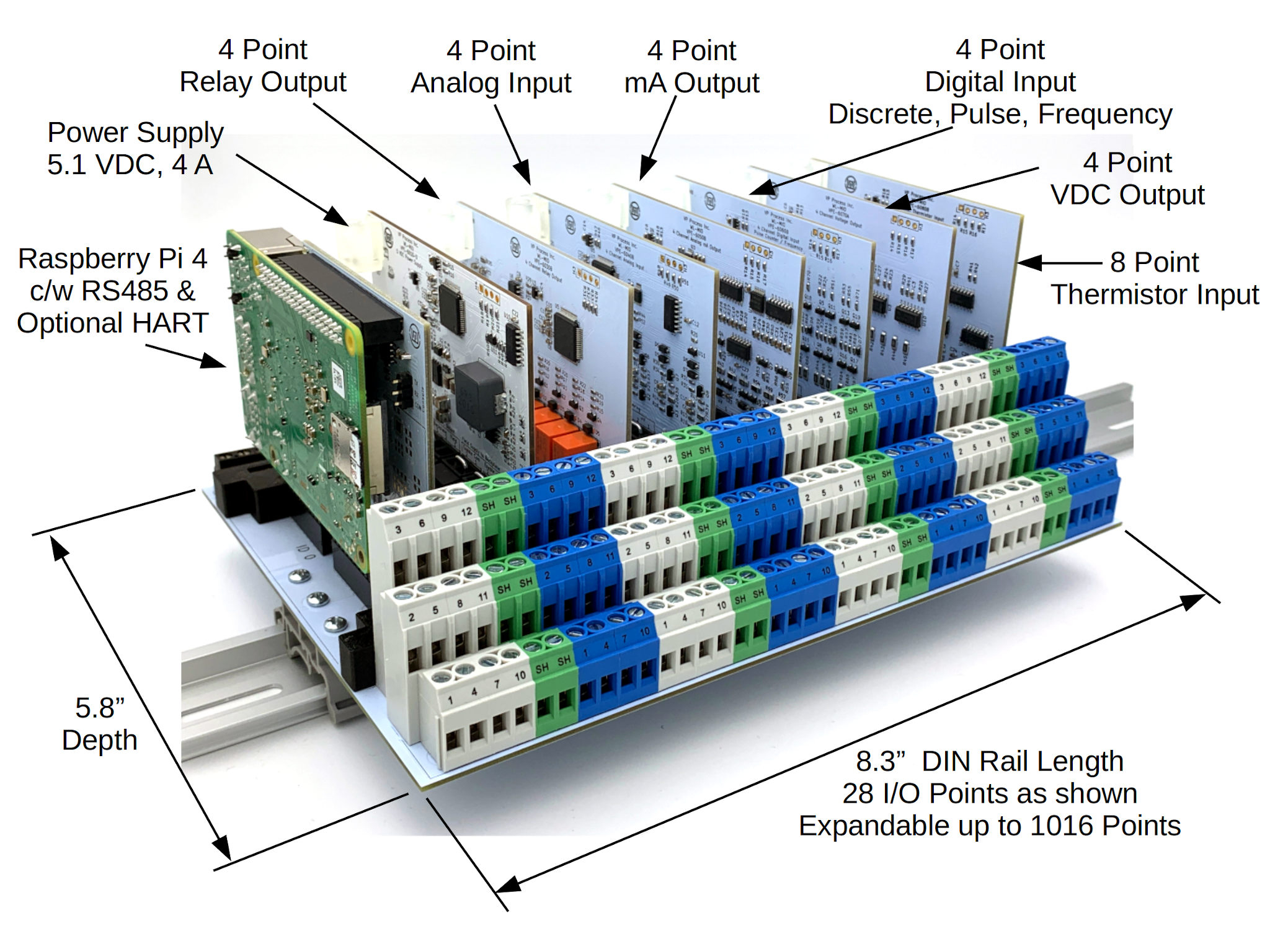
The WL-MIO Multipurpose I/O Process Controller
“The Power Under The Hood”