Relay Matrix 8x8 Application
The VPE-5020-8x8 Relay Matrix is a versatile switch matrix that can be used for designing and implementing custom switching networks for test equipment setups, process control signal routing, or any application that requires simple signal routing.
The matrix uses solid state relays with isolated contacts, and is configured in a 8 (X) by 8 (Y) configuration. Any X relay can be joined to any Y relay in any combination.

The matrix kit comes with 2 x 16 point break out modules for X and Y ports. Power is typically 24 VDC, the main communication is via Modbus RTU RS485. the simple user interface allows for Modbus ID programming and Baud rates selection from 9600 Baud to 115200 Baud.

In the test setup shown above, the test rig consists of the Raspberry Pi 4 and the PI-SPI-DIN-RTC-RS485 which has a RS485 port. Connection between the relay matrix and the PI-SPi-DIN-RTC-RS485 is via a standard Cat5e cable which carries the 24 VDC input power and the RS485 signals. The pinout is shown the above diagram.
The breakout modules provide a simple connection between the relay contacts in the X and Y ports. The pinouts for the breakout modules are also shown in the above diagram.
The operation of the matrix is very simple: any port K relay contact can be connected to any port Y relay contact.
For example: Relay X3 contact needs to be connect relay Y8 contact, turn on relays X3 and Y8.
Using this method, the relay matrix can be expanded to very large systems, here is an example of a 16 x 16 relay matrix configuration:

Specifications:
-
Power 12 to 24 VDC
-
Communications: Modbus RTU Protocol over RS485
-
Addresses: Modbus ID 1 thru 255
-
Functions 01, 02 and 15
-
User Interface UP, ENTER, DOWN Pushbuttons
-
Programmable Modbus ID and Baud rates from 9600 to 115K
-
LCD Display 128x64 to show X and Y matrix connectivity
-
Dimensions: 7" (DIN length) x 4"
-
DIN Rail mountable (DIN clips included)
-
Processor: Raspberry Pi RP2040
-
64 Relay Outputs: Solid State (Isolated) NO contact (TLP241A)
-
Relay Contact Rating: 0 to 40 VDC, 2A, On Resistance = 150 mOhms
User Interface
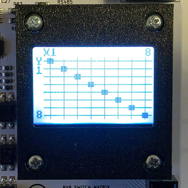
The user interface consists of three pushbuttons (UP, ENTER, DOWN) and a 128x64 graphic lcd display. The display shows the X and Y possible connections with a solid square representing the current joined X and Y connections.
The Modbus ID and Baud Rate are also programmable.
Sample Python Code
The above display and X Y configuration used the following Python code on a Raspberry Pi 4 and the PI-SPI-DIN-RTC-RS485 Interface.
Step One: Ensure the minimalmodbus library is installed for the following code to work
Step Two: Run the modbusd program as follows:
Open a terminal window
run the command:
./modbusd -d 25 -s /dev/serial0
More information on the modbusd program can be found at the application page
https://widgetlords.com/pages/rs485
Here is the sample code:
#!/usr/bin/env python3
import minimalmodbus
import time
ko = minimalmodbus.Instrument('/tmp/modbus', 1) # port name, slave address (in decimal)
ko.serial.baudrate = 9600
while True:
ko.write_bits(0,[1,0,0,0,0,0,0,0]) # Y1 X1 ON
time.sleep(.1)
ko.write_bits(8,[0,1,0,0,0,0,0,0]) # Y2 X2 ON
time.sleep(.1)
ko.write_bits(16,[0,0,1,0,0,0,0,0]) # Y3 X3 ON
time.sleep(.1)
ko.write_bits(24,[0,0,0,1,0,0,0,0]) # Y4 X4 ON
time.sleep(.1)
ko.write_bits(32,[0,0,0,0,1,0,0,0]) # Y5 X5 ON
time.sleep(.1)
ko.write_bits(40,[0,0,0,0,0,1,0,0]) # Y6 X6 ON
time.sleep(.1)
ko.write_bits(48,[0,0,0,0,0,0,1,0]) # Y7 X7 ON
time.sleep(.1)
ko.write_bits(56,[0,0,0,0,0,0,0,1]) # Y8 X8 ON
time.sleep(.1)
time.sleep(1)