


Pi-SPi-DIN-RTC-RS485 Raspberry Pi I/O Module
Regular price
$52.75 USD
This Raspberry Pi I/O Module Industrial Interface from VP Process Inc. supports the Raspberry Pi 3, 4 and 5 Series. The PI-SPI-DIN-RTC-RS485 provides a convenient support structure for the Raspberry Pi which includes basics like:
- Power Input 24 VDC (Most typical power input in automation applications)
- RPi Power 5.1 VDC @ 4A Max
- RS485 Port
- Buffered I2C Port
- Buffered SPI Port (Chip Selects C0, 1, 2, 3 and 4)
- Real Time Clock with CR2032 Battery Backup
Four mounting versions are available:
- -PCB Printed Circuit Board Assembly c/w Ribbon Cables
- -CLIP Same as PCB with DIN clips for DIN Rail mounting
- -ENC Horizontal DIN Rail Mount Enclosure
- -V Vertical DIN Rail Mount Enclosure c/w Pluggable Terminal Blocks
Block Diagram

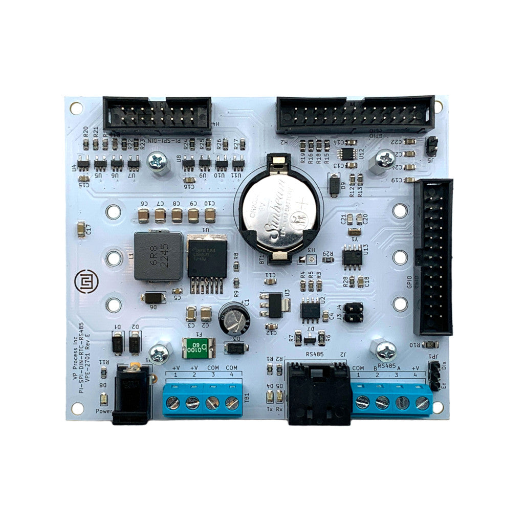
-PCB Option - Revision E (Current Release)

DIN Rail Mounting Clips

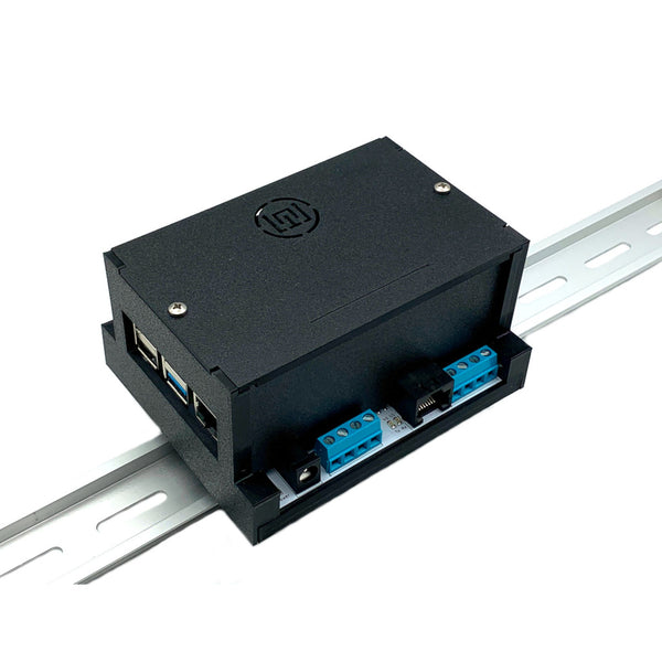
- ENC Option Horizontal DIN Rail Enclosure - Black (Standard)
-V Option Vertical DIN Rail Enclosure

-V Option shown open with Raspberry Pi 5 Module (RPI Modules NOT Included)

Specifications:
- Power Input: 9 to 24 VDC (28 VDC Max)
- Power Input: Barrel Plug or Terminal Block
- Blue LED Power Indicator
- 5VDC @ 2.5A (Max 3Amp) Power Supply
- Power To Raspberry Pi module supplied via GPIO Ribbon Cable (26 Pin)
- RS485 Output via RJ45 connector and Terminal Block
- RS485 uses GPIO Uart and 1 GPIO pin for direction control
- RS485 can be disconnected via jumpers
- Local RS485 Termination resistor - Enabled via jumper
- RS485 Tx/Rx LED Indicators
- 2 GPIO connectors - 1 internal for Raspberry Pi, 1 external for peripherals
- 1 PI-SPI-DIN connector (16 Pin) for PI-SPI-DIN series (power, SPI, I2C and 5 Chip Enables)
- Real Time Clock (I2C) Microchip MCP7940
- Battery Coin Cell Holder for CR2032 battery (Included)
- PCB Dimensions: 4" Wide x 3.4" High
- Terminal blocks are rising cage clamp style
- Complete factory test
NOTE: Raspberry Pi Module NOT Included
Node-RED
The PI-SPI-DIN Series now has Node-RED support. Please visit
![]() Node-RED and the PI-SPI-DIN Series
Node-RED and the PI-SPI-DIN Series
for instructions.
Contact us for more information or custom configurations. All designs, engineering and manufacturing are done at our factory, Kelowna, British Columbia, Canada.
PI-SPI-DIN GPIO Connector Pinout

The PI-SPI-DIN Series of peripheral modules are designed to "Daisy Chain" from the main PI-SPI-DIN-RTC-RS485 module.
Three modules rely on the SPI buss - the 8AI, 8DI and 4KO modules.
- the 8DI and 4KO modules use a GPIO expander chip (MCP23S08) as described above
- the 4AO 4-20mA analog output module uses the I2C buss and the DAC used (MCP4728) can be programmed for different I2C addresses
A typical daisy chained system maxing out the hardware provided chip selects (without "hacking" the boards to use other GPIO pins as chip selects) would be as follows:
3 x PI-SPI-DIN-8AI modules for a total of 24 x 4-20 mA Inputs (GPIO7, GPIO23 and GPIO18)
4 x PI-SPI-DIN-4AO modules for a total of 16 x 4-20 mA Outputs (I2C bus)
4 x PI-SPI-DIN-4KO modules for a total of 16 SPDT 2A Contact Relays (GPIO8 and 4 Jumper selectable addresses on the modules A0 thru A3)
4 x PI-SPI-DIN-8DI modules for a total of 32 Isolated Digital inputs (GPIO24 and 4 Jumper selectable addresses on the modules A0 thru A3)
That is 15 modules for a total of 88 I/O points, all powered form the main module.

Downloads
 PI-PSI-DIN-RTC-RS485 Schematic
PI-SPI-DIN-RTC-RS485 PCB Layout
Real Time Clock Using the MCP7940 for the Raspberry Pi
For Python Sample Code, please visit: