SDAFE-HART Software Defined Analog Input Module with HART I/O Module
Regular price
$59.95 USD
Each SDAFE™ Analog Input I/O Module can be programmed thru the application software to be 4-20 mA, 1 to 15 VDC or 0 to 10 VDC input. All modules are factory calibrated with 6 break point calibration per input type.
Typical resolutions are +/- .005 mA for 0 thru 20 mA. +/- .005 VDC for 0 to 5 VDC and 0 to 10 VDC Inputs.
The SDAFE™ communicates via SPI, and is powered from a single +3.3VDC or +5VDC source. The A/D converter is a 15 bit A/D.
The HART compatible modem allows the attached HART enabled transmitter to communicate with the RPi via the GPIO Uart.
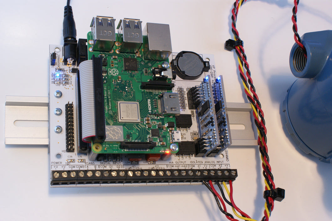
The SDAFE-HART is compatible with the:
PI-SPI-DIN-2x4MIO I/O Module and the PI-SPI-DIN-RTC-RS485-4AI-4KO-8DI I/O Module
Please allow 2 weeks for order processing.
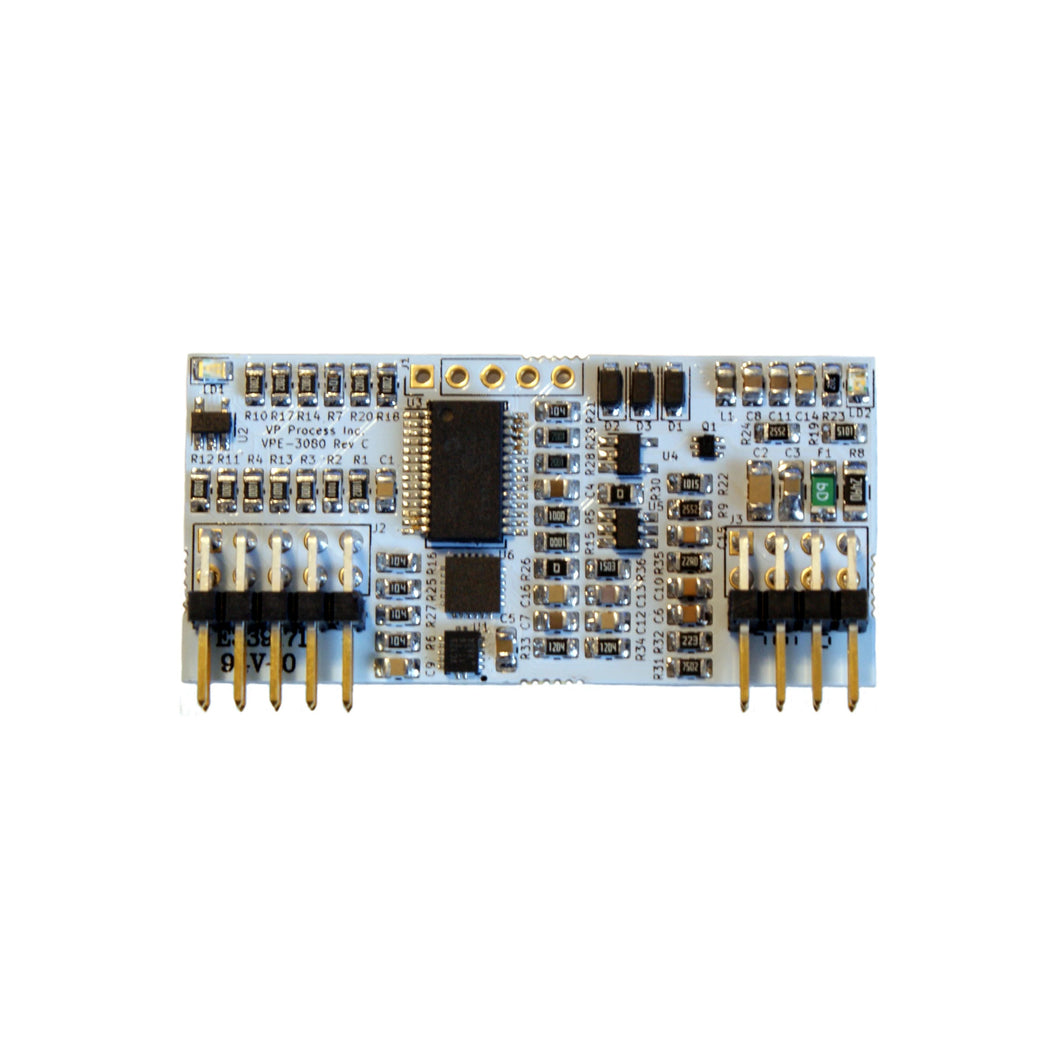
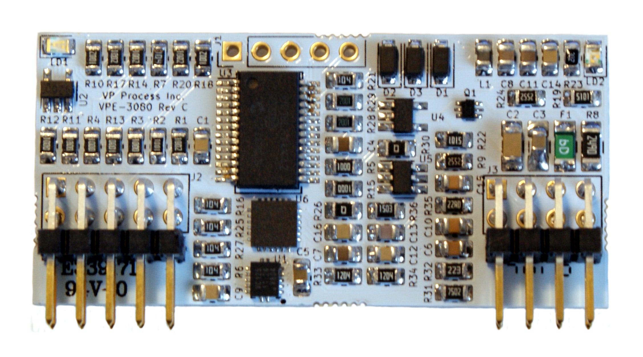
Non-Isolated SDAFE-HART Model VPE-3080C
Standard Ranges:
- 0 - 20 mA
- 0 - 5 VDC
- 0 - 10 VDC
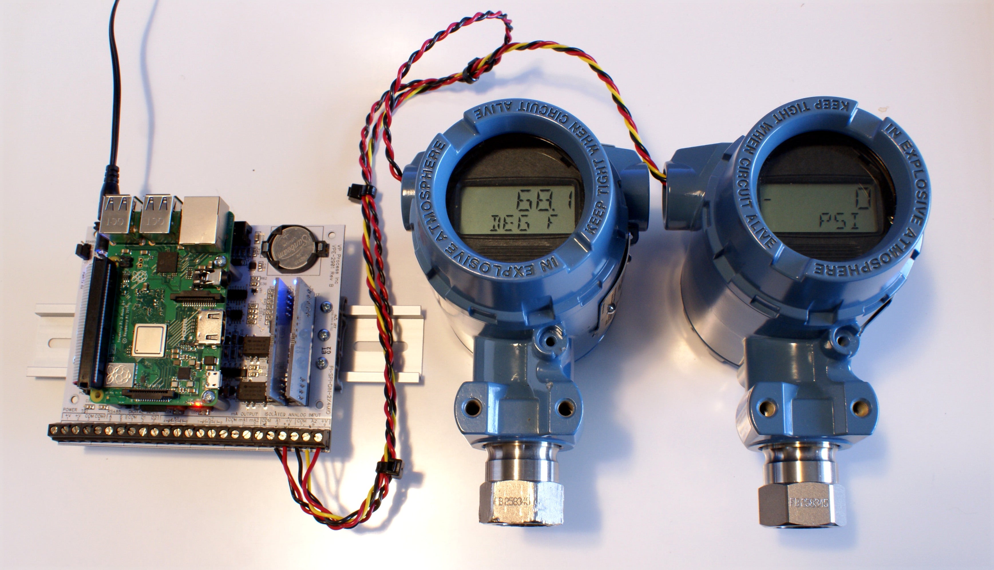
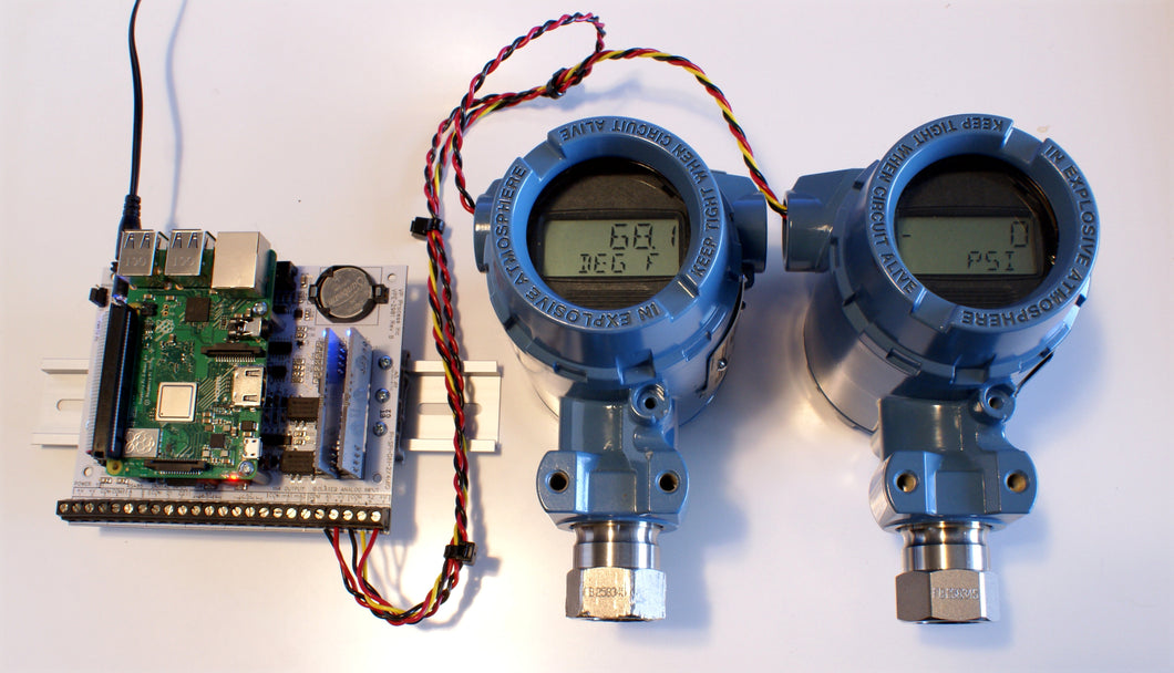
Two Rosemount 2880 HART enabled transmitters talking to a RPi3 B+ using the SDAFE-HART I/O Module.
Specifications:
Power:
3.3VDC or 5.0VDC (Raspberry Pi and Arduino Compatible)
SPI:
MISO Data Input, Active High
MOSI Data Output, Active High During Chip Select, Open Collector Output
SCK Clock
/CS Chip Select, Active Low
Speed Up to 100KHz
Input:
Type 1: (Default) 0 - 20 mA 0 - 20000 Units: mA
Type 2: 0 - 20 mA 0 - 10000 %
Type 3: 4 - 20 mA 0 - 10000 %
Type 4: (Default) 0 - 5 VDC 0 - 5000 Units: VDC
Type 5: 0 - 5 VDC 0 - 10000 %
Type 6: 1 - 5 VDC 0 - 10000 %
Type 7: (Default) 0 - 10 VDC 0 - 10000 Units: VDC
Type 8: 0 - 10 VDC 0 - 10000 %
Type 9: 2 - 10 VDC 0 - 10000 %
AD Converter:
Resolution: 15 bits
Conversion:
15 SPS (Samples per Second)
Accuracy:
+/- .005 reading for mA and VDC Types 1, 4 and 7
+/- .01 reading for mA and VDC Types 2, 3, 5, 6, 8 and 9
Over Range:
Inputs have up to 25% Over Range per input type
Error Status:
Status Register: Over Range Detection when input greater than 125%
Reverse Polarity Detection
Indicators:
Blue LED: Power ON
Green LED: ON When Chip Select Active (Low)
Connections:
J2 Non-Isolated Side
Pin 1: +V (+3.3VDC or +5VDC)
Pin 2: 0V (Common)
Pin 3: MOSI
Pin 4: CLK
Pin 5: /SS (Chip Select)
Pin 6: MISO
Pin 7: Reserved for HART Module
Pin 8: Reserved for HART Module
Pin 9: Reserved for HART Module
Pin 10: Reserved for HART Module
J1
Pin 1: no connection
Pin 2: no connection
Pin 3: Common
Pin 4: Common
Pin 5: Signal Input mA or VDC
Pin 6: Signal Input mA or VDC
Pin 7: Common
Pin 8: Common
Dimensions:
1.95" x 0.95"
Headers on standard 0.1" spacing
Typical Screenshot of the Python Demo Software:
