Relay Matrix 8x8 KIT
Regular price
$295.00 USD
Sale
The VPE-5020-8x8 Relay Matrix is a versatile switch matrix that can be used for designing and implementing custom switching networks for test equipment setups, process control signal routing, or any application that requires simple signal routing.
The matrix uses solid state relays with isolated contacts, and is configured in a 8 (X) by 8 (Y) configuration. Any X relay can be joined to any Y relay in any combination.
These modules can be expanded by simply adding more interfaces and connecting the Y to Y ribbon cable connection and X to X ribbon cable connection. For example, with 2 VPE-5020-8x8, you can create a 16 x 8 matrix, or a 8 x 16 matrix. With 4 units, you can create 16 x 16 matrix, etc.
Specifications:
- Power 12 to 24 VDC
- Communications: Modbus RTU Protocol over RS485
- Addresses: Modbus ID 1 thru 255
- Functions 01, 02 and 15
- User Interface UP, ENTER, DOWN Pushbuttons
- Programmable Modbus ID and Baud rates from 9600 to 115K
- LCD Display 128x64 to show X and Y matrix connectivity
- Dimensions: 7" (DIN length) x 4"
- DIN Rail mountable (DIN clips included)
- Processor: Raspberry Pi RP2040
- 64 Relay Outputs: Solid State (Isolated) NO contact (TLP241A)
- Relay Contact Rating: 0 to 40 VDC, 2A, On Resistance = 150 mOhms
VPE-5020-8x8-KIT
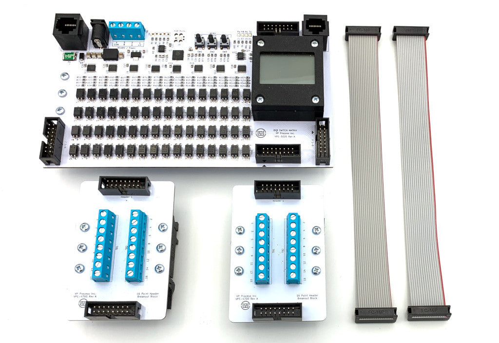
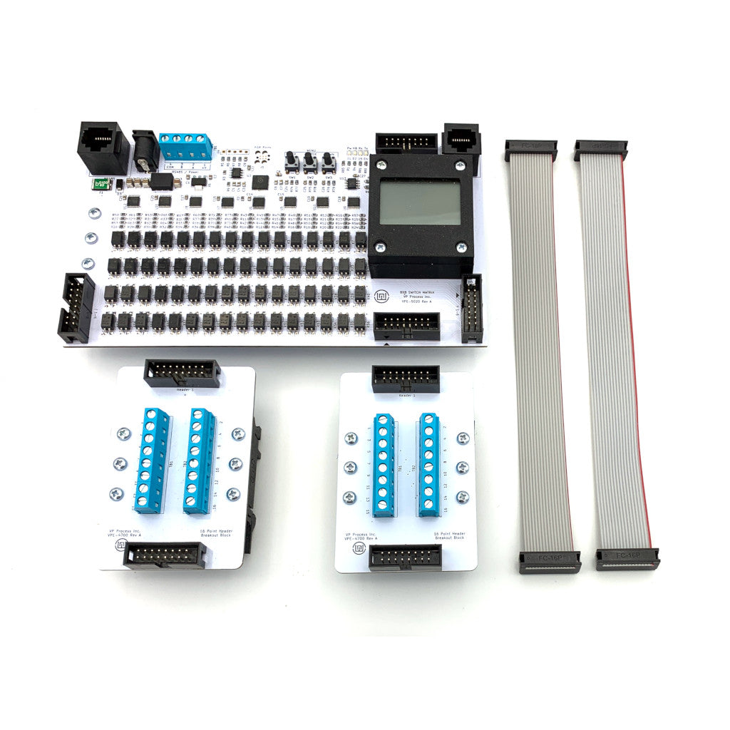
The kit comes complete with one VPE-5020-8x8 matrix module with DIN clips, qty 2 breakout modules with DIN clips, and qty 2 ribbon cables for connecting to the X and Y matrix.
VPE-5020-8x8 Module

The module was designed for simple expansion - the Y to Y and X to X ribbon cable connections are mirrored on both side of the board. Power (24VDC Typical) is applied via the barrel jack or terminal block. The RS485 (Modbus RTU Protocol) is applied via the terminal block, or via the RJ45 connectors. Power and RS485 via the RJ45 connectors allow simple connectivity between modules using standard Ethernet cables.
More information can be found on the application page:
User Interface
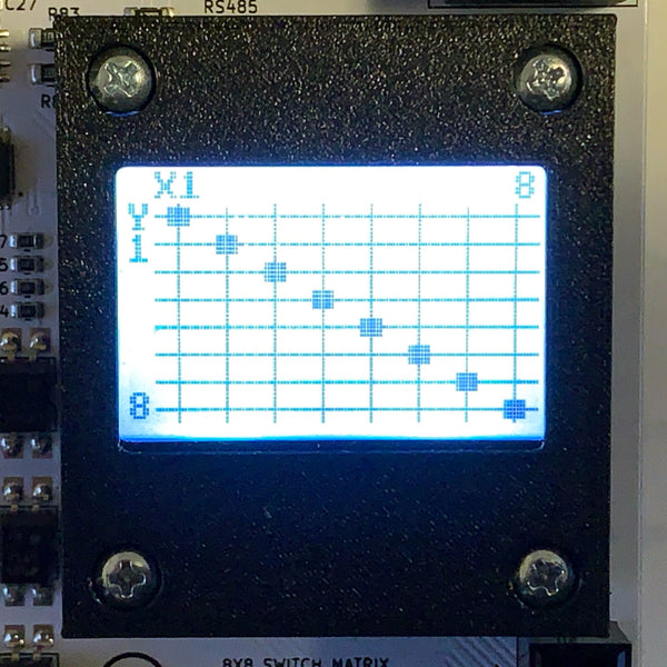
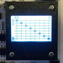
The user interface consists of three pushbuttons (UP, ENTER, DOWN) and a 128x64 graphic lcd display. The display shows the X and Y possible connections with a solid square representing the current joined X and Y connections.
The Modbus ID and Baud Rate are also programmable.
Sample Python Code
The above display and X Y configuration used the following Python code on a Raspberry Pi 4 and the PI-SPI-DIN-RTC-RS485 Interface.
NOTE: minimalmodbus must be installed for the following code to work
the modbusd program must also be run prior to running the following example
#!/usr/bin/env python3
import minimalmodbus
import time
ko = minimalmodbus.Instrument('/tmp/modbus', 1) # port name, slave address (in decimal)
ko.serial.baudrate = 9600
while True:
ko.write_bits(0,[1,0,0,0,0,0,0,0]) # Y1 X1 ON
time.sleep(.1)
ko.write_bits(8,[0,1,0,0,0,0,0,0]) # Y2 X2 ON
time.sleep(.1)
ko.write_bits(16,[0,0,1,0,0,0,0,0]) # Y3 X3 ON
time.sleep(.1)
ko.write_bits(24,[0,0,0,1,0,0,0,0]) # Y4 X4 ON
time.sleep(.1)
ko.write_bits(32,[0,0,0,0,1,0,0,0]) # Y5 X5 ON
time.sleep(.1)
ko.write_bits(40,[0,0,0,0,0,1,0,0]) # Y6 X6 ON
time.sleep(.1)
ko.write_bits(48,[0,0,0,0,0,0,1,0]) # Y7 X7 ON
time.sleep(.1)
ko.write_bits(56,[0,0,0,0,0,0,0,1]) # Y8 X8 ON
time.sleep(.1)
time.sleep(1)
'

